

Ten Options for Sediment Management at Intakes
- Edmund Atkinson

- Apr 21
- 9 min read
Updated: May 4
This first article in the series will look at ten options available when sediment ingress
at an intake is problematic. They are ordered from upstream in the river catchment
to downstream in irrigation canals. It concludes with a Preliminary Screening
Matrix giving some advantages and disadvantages for each option, the kind of
sediments it controls and a generalised ‘traffic light’ assessment.
The options are:
10. Canal de-silting
1. Catchment conservation
This option deals with the root cause, but it is not viable. Soil conservation
programmes in a river catchment upstream from the intake will not rapidly reduce the river sediment loads. The reason is the vast store of sediments available for
remobilization in catchments that have suffered from high rates of soil erosion in the
past, this store will continue to contribute to downstream sediment loads for long
periods, decades or even centuries. In addition, measures such as re-forestation
programmes take time to implement and establish their impacts.
2. Location of River Intakes
Moving the location of an intake is an expensive option but worth considering,
especially for coarser sediments. Ideally a river intake should be sited at the outside
of a river bend, just downstream from the section of maximum curvature. At the
outside of a bend the deep water channel is established close to the bank, which
usually ensures trouble free abstraction of low flows. Meanwhile the secondary
currents minimise the abstraction of coarse sediments, which are swept along the
channel bed towards the inside of the bend, see Fig 1. It is the relatively sediment
free surface flow which is abstracted.

Sediment shoals often form at the entrance to a badly sited intake, for example
intakes located at the inside of a river bend. These hinder diversion of low flows, and
in extreme cases can cut off the intake from the river. Correct siting of an intake is
the first, and usually the most important step to minimise the diversion of coarse
sediments.
At intakes where there is no barrage or weir across the river to control the flow, then
there is no head difference available to drive sediment control measures, hence the
intake location becomes even more significant.
3. River training to improve the alignment of the flows approaching the intake.
It might be feasible to induce beneficial flow curvature using embankments and
spurs in a river. An example is at Sukkur Barrage, Pakistan. Fig 2 shows the training
works implemented in the 1940s in response to sedimentation in the right bank
canals, note the curvature of the “Approach Channel”. The original structures are
shown in black and the 1940s works in green. The new training works involved
closing several barrage gates which in theory would reduce the ability of the barrage to safely pass historic floods. The engineers assessed that the risk was acceptable, subsequent experience and analysis using numerical models have so far proved them correct.
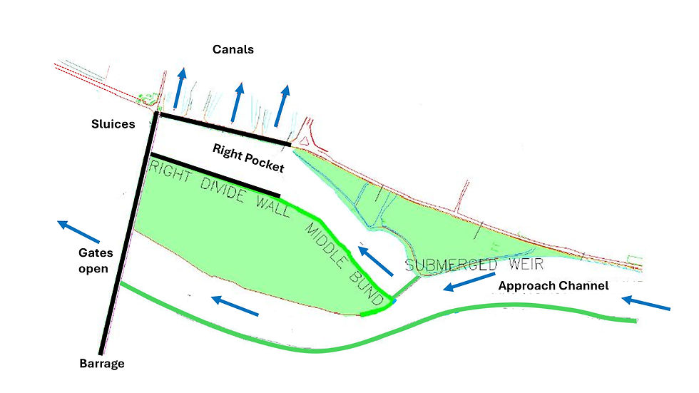
At Sukkur the training works did not re-align the whole Indus river, just the flows
approaching the right bank intakes. Re-training a whole river to induce the beneficial
curvature seems impracticable.
The advantage of intakes which divert water at both banks of rivers is how one
diversion weir or barrage then supplies two canal systems, as at Sukkur. But it can
be difficult to provide the correct approach flow conditions at both sides of the river. Artificial islands have been constructed to create curved approach flows for both sides of a river.
In steep rivers the upstream bed levels rapidly rise to the crest level of the diversion
weir, which can lead to problems in stabilising the position of the low flow channel.
This can be overcome by regular operation of the sluice gates, when sufficient
sluicing capacity, and excess water, is available. Weirs with a small cross-fall
towards the sluice and canal intake have been used to ensure that the main river
channel develops close to the canal intake.
Training works more immediately local to the intake may also be considered, such as
Kings Vanes as shown in Fig 3. The vanes protrude up from the river bed, but the
variations in river bed level in a morphologically active river will make their impact
variable and perhaps not reliable.

4. Closing the intake gates during river floods
Often a large proportion of the annual sediment load entering an intake occurs
during river floods. The cost-benefit balance may be in favour of closing intake gates during periods of high river discharge. In the case of irrigation, the floods may be associated with high rainfall in the irrigation service area and so the penalty of closing canal head gates is diminished.Often a large proportion of the annual sediment load entering an intake occurs during river floods. The cost-benefit balance may be in favour of closing intake gates during periods of high river discharge. In the case of irrigation, the floods may be associated with high rainfall in the irrigation service area and so the penalty of closing canal head gates is diminished.
5. Sediment exclusion at intakes
Sediment excluders are structures which actively divert the high sediment flow near
the river bed away from the intake and ensure only relatively sediment-free water in
the upper layer is withdrawn into the intake. Typical river intakes incorporating
sediment excluders are shown in Figs 4 and 5.


Sediment excluders are designed for continuous operation and they are used in
rivers where the flow is larger than the abstraction requirement during periods when
high sediment loads are transported.
Separation of the upper and lower layers of the flow is achieved by:
Incorporating a tunnel under-sluice, (Tunnel excluder, Fig 4), so that it is impossible
for water and sediment from the bed layers to be diverted to the canal.
Incorporating a curved channel, (Curved channel excluder, Fig 5), so that flow and
coarse sediments in the bed zone are swept away from the intake gates. Structures
in the river can also be used to induce flow curvature, Fig 6, but these may change
behaviour as conditions change, such as in high river flow.
Setting the sill level of the canal intake well above the level of the sluice-way,
(conventional intake), and operating with the sluice gates partially open so that the
lower layer of river flow passes below the canal intake and through the sluice gates.
If the intake is a weir, this arrangement is called a skimming weir. This is
considerably less effective than using tunnels or curved channels, as bed flow can
still rise up and flow into the intake.

Sediment excluders do little to exclude finer sediments that are suspended
throughout the depth in the river flow. They are thus only likely to offer a solution to
sedimentation problems when the sediments settling in the channels or damaging
turbines are fairly coarse.
Sediment exclusion options where there is no weir or barrage are restricted to
inducing flow curvature, skimming weirs or overshot intake gates so that the top
water carrying the smallest sediment concentrations and the finest sediments are
diverted. Pumped intakes can be designed to take near-surface flow, such as with
floating inlets.
6. Flushing and “still pond operation”
Another method of managing sediment at the intake is where sediment flushing is
carried out intermittently, it is often called “still pond operation”. It is used at intakes
with conventional sluice gates. An essential feature is a Sluicing Channel that forms
a settling area upstream from the intake and sluice gates, see Fig 7. At intakes
designed for this operation the water velocity in the Sluicing Channel is lower than
the average velocity in the river upstream. Coarser sediment fractions in the flow
approaching the canal intake gates thus settle in the channel.

After a period of sediment deposition in the sluice channel the bed levels will rise
such that sediment will start to be drawn into the intake, the sluice gates are then
opened. The sediment deposits are thereby flushed through the sluice gates. During flushing the intake is temporarily closed. This style of operation works best in rivers where the sediment loads are not too large, so that sediment flushing is not required more often than about once a day. The temporary intake closures must be
acceptable.

The term “still pond operation” is common in south Asia and is usually associated
with a layout such as sketched in Fig 8. The embankment dividing the sluicing
channel from the river in Fig 7 is replaced by a wall in Fig 8, called the Divide Wall.
The sluicing channel itself is called the Pocket. However, a common feature is the
inadequate length of the Divide Wall which produces insufficient storage for the still
pond operation to provide any significant sediment control.
7. Physical screens and grilles
In mountain streams the sediment can be dominated by very large material which
can be kept from being abstracted with a physical barrier. A good example is the
Tyrolian weir type intake, Fig 9, the weir itself is shown in long-section in Fig 10. The
bars sit on the back face of the weir and align with the flow, so large stones, rocks
and boulders roll above the bars and only finer material passes between the bars.
In this arrangement the flow passes laterally into a chamber beside the weir and then into the intake.


Finer screens or filters can also be used, often with movement or back washing, but
they are unlikely to be appropriate for large scale abstractions.
8. Settling basins or chambers
Settling chambers can be used immediately after the point of diversion within the
intake structure, as shown above in Fig 9. Or settling basins can be placed at the
head of the offtake channel and are formed as an enlarged canal cross section. A
typical settling basin layout at the head of an irrigation canal is shown in Fig 11.

Within the basin or chamber, the flow velocities are reduced to ensure that sediment
settles and is trapped in the basin. Where the conditions are suitable sediment
deposits are flushed back to the river via a low level sluicing outlet located at the
downstream end of the basin. Where flushing is not feasible sediment is removed
using mechanical plant. Twin basins are sometimes used, so that sediment removal
can be carried in one basin while the second continues the supply of water.
For a certain abstracted discharge, increasing the size of the basin or chamber
causes finer material to be trapped, thus these structures are suitable for controlling the fine sands which other methods cannot address.
9. Sediment extractors
Sediments in the sand size range are normally transported in suspension in rivers at
medium and high discharges, and as they are quite well mixed in the river flow, are
typically not controlled effectively by sediment excluders. If sediments in the sand
size range are settling in a canal network, then sediment extractors can be a suitable
option.
A tunnel type sediment extractor is shown in Fig 12, it consists of a row of tunnels
placed at the bed of a canal that divert water and sediment flowing near the bed.
High velocities are necessary in the tunnels to prevent sediment deposition. The
basic principle is the same as for tunnel type sediment excluders, which is that
significantly higher sediment concentrations flow near the channel bed. But the flow conditions in the canal headreach are more quiescent than in the river, which causes extractors to have higher performances than excluders for sand sizes.

Fig 13 shows another means of extraction, the vortex tube sediment extractor, which
consists of one or more slotted tubes laid flush with the canal bed. One end of the
tube is closed, the other is open and connected to an escape channel. Water and
sediment flowing near the bed of the channel upstream is diverted through the vortex tube. A strong vortex flow is developed in the tube, which, provided the tube
dimensions have been chosen correctly, prevents sediment from settling and
blocking the tube.

In most cases the extracted flow is returned to the river in an escape channel, see
Fig 14. The layout shows how a long near-straight canal reach is needed upstream
from the extractor to enable suspended sediments to settle near the channel bed.

10. Canal de-silting
In some cases de-silting will be the only feasible option or the most cost-effective
means of sediment management in irrigation systems, and in other cases it may be
one component of a sediment control strategy.
If the desilted material can be sold or removed free of charge then it will become a
more attractive option.
Preliminary Screening Matrix
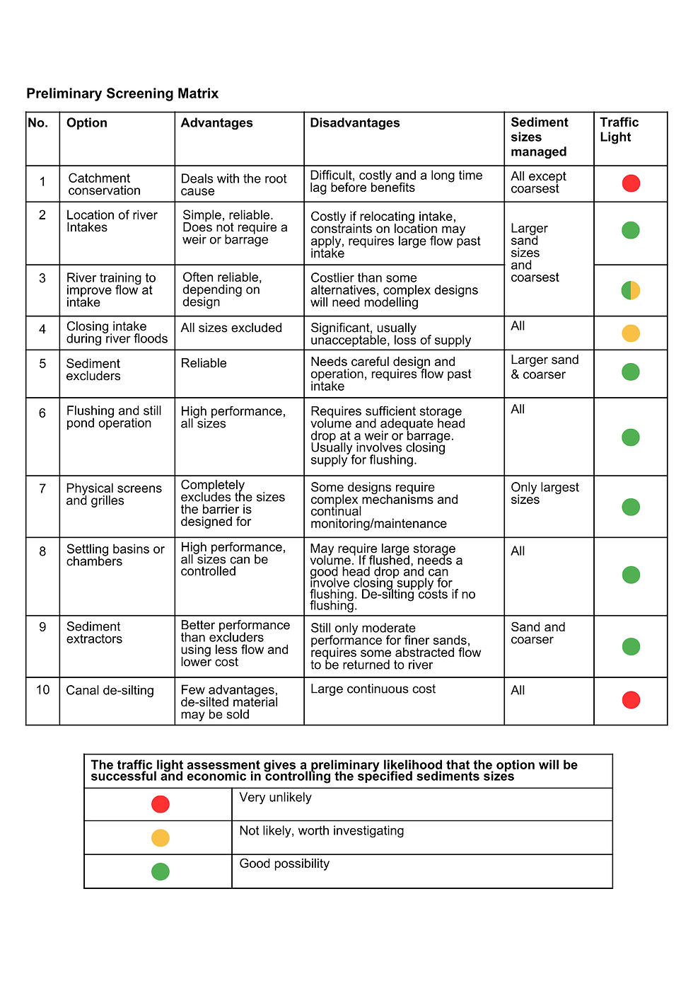
Click to download the Preliminary Screening Matrix.
Note: This matrix provides a high-level comparison for preliminary screening. The
suitability of each option depends heavily on site-specific factors and constraints.
Future articles will cover these.
Comments